- Engineering
- Measuring systems
- Machine qualification
-
Components
-
Systems
-
Learn more
-
- Expertise
-
About IBS
-
Our Story
-
Learn More
-
Learn answers to frequently asked questions about our inductive measurement systems. Discover unique features and customer benefits and understand how these systems can help you achieve unmatched precision in distance, position and motion measurement.
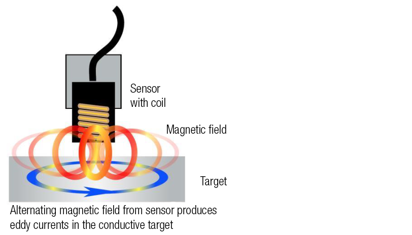
Inductive sensor operation relies on the relationship between electric current and magnetic fields. Inductive probes contain a coil that is excited with alternating current, creating an alternating magnetic field ( Ampère’s law). When these magnetic fields interact with a conductive target, electric currents (eddy currents) are induced in the target material. The eddy currents in the target act in opposition to the original magnetic field ( Lenz’s law). In order to maintain the original magnetic field around the sensing coil, the excitation current in the coil is increased. This interaction between the fields is used by the signal processing electronics to generate an output voltage proportional to the gap. This can be measured at speeds up to 80kHz. Thus the inductive sensor may be used for high resolution, high speed, non-contact distance measurement.
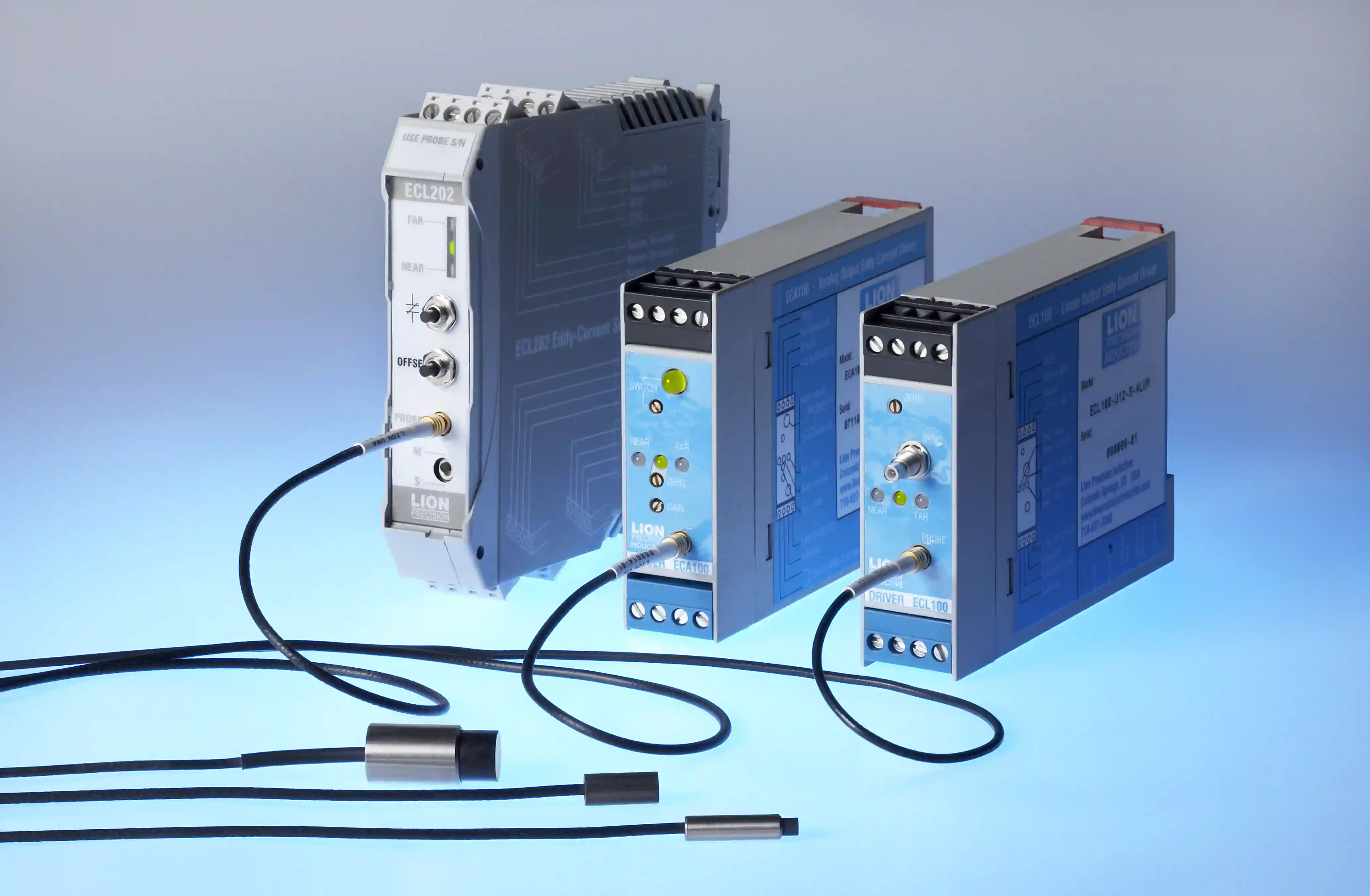
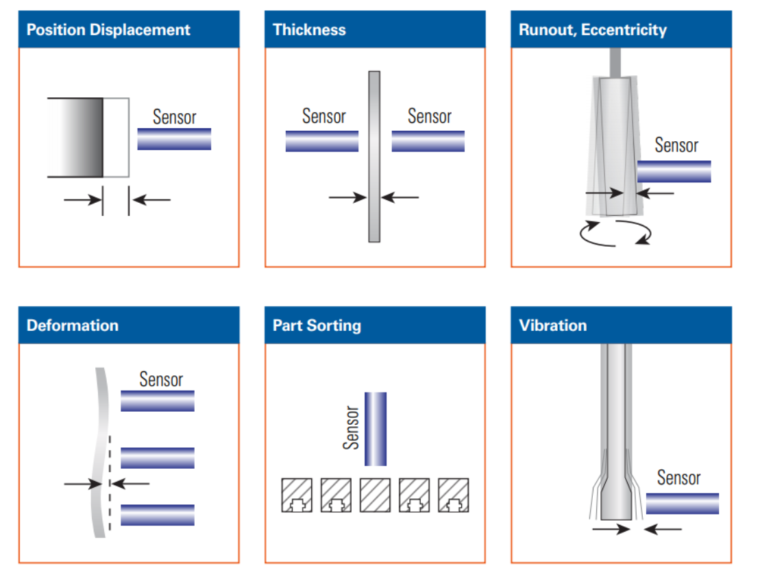
Our high performance Eddy current sensors offer the best resolution available in an industrial environment. They are ideal for measuring high speed linear motion or rotating targets for example: valve stroke; shaft concentricity, axial or relative displacement; spindle thermal growth or vibrations; liquid gaps; measurement through foils; detection of moving objects for process control. They are suitable for pressurised or nuclear environments and can address large temperature ranges. With bandwidths up to 80kHz (ECL101) they can be used for high speed applications in rotary and linear applications. Resolutions down to 10nm at 1,5kHz can be achieved (EDA400) for high precision measurement.
Systems such as the ECL202 also include switched output which can be triggered at a chosen gap values for external control. For further example applications see our Inductive Sensors Applications.
The electronics in a sensor are calibrated to generate specific voltage changes for corresponding changes in inductance. These voltages are scaled to represent specific changes in distance. The amount of voltage changes for a given amount of distance change is called the sensitivity. A common sensitivity setting is 1.0V/100μm. That means that for every 100μm change in distance, the output voltage changes exactly 1.0V. With this calibration, a +2V change in the output means that the target has moved 200μm closer to the probe.
Sensors are factory calibrated for the chosen range and a traceable calibration certificate provided. The calibration system delivers positional accuracies of less than 0.012μm uncertainty and is certified on a regular basis with a NIST traceable laser interferometer. Calibration certificates conform to section 4.8 of ISO 10012-1.
Resolution is defined as the smallest reliable measurement that a system can make. The resolution of a measurement system must be better than the final accuracy the measurement requires. If you need to know a measurement within 0.02μm, then the resolution of the measurement system must be better than 0.02μm. The primary determining factor of resolution is electrical noise. The amount of noise in the output is directly related to bandwidth. When examining resolution specifications, it is therefore critical to know at what bandwidth the specifications apply.
The resolution of inductive sensors varies between ferrous and non-ferrous materials. Non-ferrous aluminium makes a good target material, offering slightly high resolutions than ferrous steel. For all sensors, we provide resolution figures at a range of bandwidths. Resolutions as low as 10nm at 100Hz bandwidth can be achieved on an aluminium target. Click here to see the specifications of the ECL202.
The range in which a sensor is useful is a function of the size of the sensing area. The greater the area, the larger the range. For inductive sensors, the ratio of the sensing range to the sensing coil diameter is 1:3. This means that for every unit of range, the coil diameter must be three times larger. For example, a 1500μm (1.5mm) diameter inductive coil will have a 500μm sensing range. This ratio is for typical calibrations. Typical probe diameter size verses range is shown below. Note the probe diameter will be larger than the coil diameter.
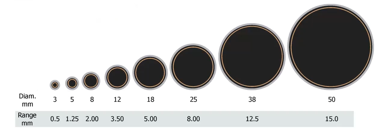
Standard ranges vary between 0.5mm and 15mm. High resolution and extended range calibrations are available on request for specific applications.
The sensing field of a non-contact sensor’s probe engages the target over a certain area. The size of this area is called the spot size. The target must be larger than the spot size or special calibration will be required. Spot size is always proportional to the diameter of the probe. For inductive sensors the spot size is 300% of the diameter of the sensing area.
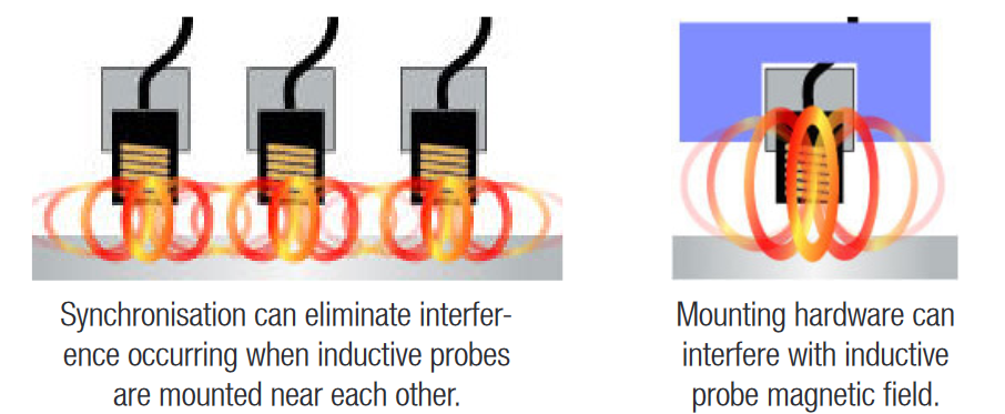
Yes you can. Frequently, a target is measured simultaneously by multiple probes. If the application requires inductive technology, special care must be taken in the mounting plan, as mounting blocks may cause interference and special calibration may be required. Driver electronics can be configured as masters or slaves. The master sets the synchronization for the slaves in multiple channel systems.
Yes they can. Magnetic fields are not affected by non-conductive contaminants such as dust, water, and oil. As these contaminants enter the sensing area between an inductive sensor and the target, the sensor’s output is not affected. So inductive sensors are the best choice when the application involves a dirty or hostile environment. It is also possible to look through plastic or glass to a target. Lion Precision inductive probes are rated at IP67 and can even be used completely immersed in non-corrosive liquid.
Yes they can. Our inductive probes have undergone testing and are proven to withstand pressures of up to 69 bar or 1000 psi.
Yes they can. All our inductive sensors are designed to be vacuum compatible to UHV on request. To make our standard sensors vacuum compatible, further to additional cleaning, the sensors are vacuum relieved to ensure no trapped gas. For vacuum applications we replace the standard cables of the inductive probes with Teflon cables and offer vacuum feedthroughs.
For ultra-precision applications it is important to consider the total metrology loop and potential influences on these loops. One of them is temperature and when comparing inductive to capacitive, the temperature generated by inductive is higher. We can advise you on this for temperature sensitive vacuum applications.
Inductive probes, because of their tolerance of hostile environments have a greater temperature range than other non-contact probes, such as capacitive sensors. Standard inductive probes, which use polyurethane cables, have an operating range from -25 to +125°C. High temperature probes, which use Teflon FEP cables, have an operating range of -25 to +200°C. Note the Teflon cable sensors are not IP67 so should not be immersed in hot liquids. With a suitable calibration applied, sensors can be operated at liquid nitrogen temperatures (−195.79 °C), for cryogenic applications.
Yes they can. As the magnetic field of the sensors penetrates the target, they are sensitive to the target material. Inductive sensors therefore need to be factory calibrated to the same material as the target in the application. Standard calibrations are available for 4140 steel and aluminium. For other target materials, such as copper or tungsten, calibration would need to be made to that material.
Note that inductive sensors should not be used with rotating magnetic material targets (such as iron or steel) unless the electrical runout errors are acceptable in the application. The high permeability of magnetic materials such as iron and steel can cause small inductive sensor errors within the same piece of material due to microscopic cracks and material variations which cause permeability changes. While the changes are relatively small, the extremely high permeability of magnetic materials enables high-resolution inductive sensors to detect these changes in rotating targets of magnetic materials.
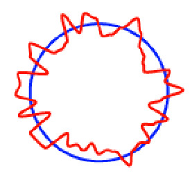
Runout plot showing actual runout in blue, electrical runout from inductive sensor in red.
The variation in output voltage with distance in a inductive sensor is not typically linear. The linearity specification is the measurement of how far the output varies from a straight line. To calculate the linearity error, calibration data is compared to the straight line that would best fit the points. This straight reference line is calculated from the calibration data using a least squares fit. The amount of error at the point on the calibration curve that is furthest away from this ideal line is the linearity error. Linearity error is usually expressed percentage of full scale. If the error at the worst point was 0.001mm and the full-scale range of the calibration was 1mm, the linearity error would be 0.1%.
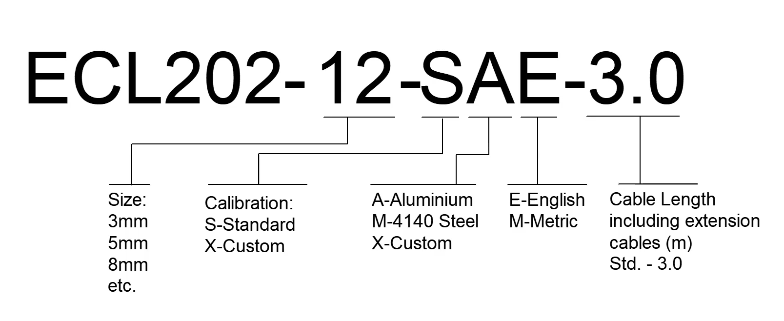
Naming structure of Lion inductive sensors: