- Engineering
- Measuring systems
- Machine qualification
-
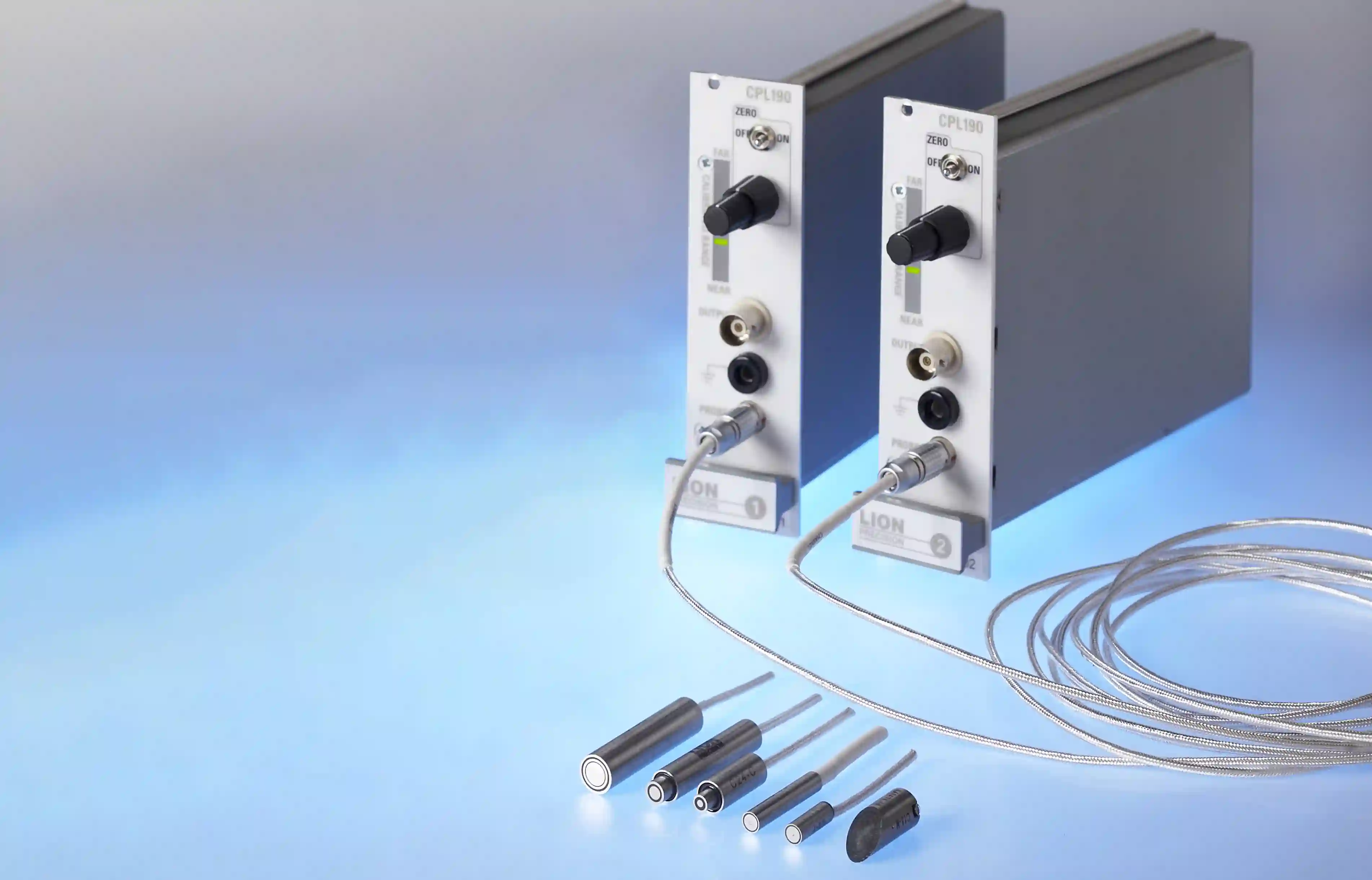
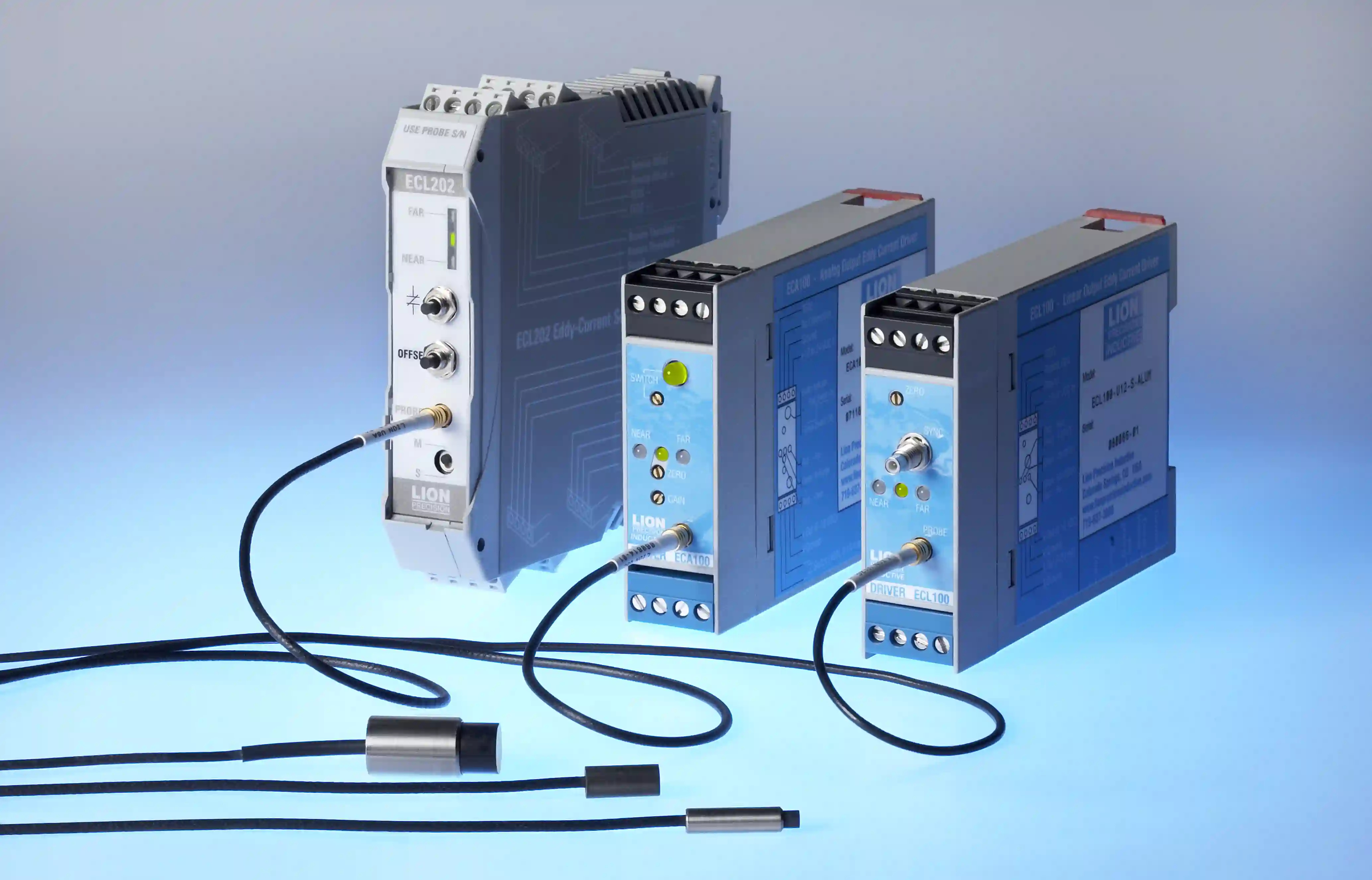
Components
-
Systems
-
Learn more
-
- Expertise
-
About IBS
-
Our Story
-
Learn More
-

Learn answers to frequently asked questions about our capacitive- and inductive measurement systems. Discover unique features and customer benefits and understand how these systems can help you achieve unmatched precision in distance, position and motion measurement.